

Cooling that runs around the clock
Servers do not clock out, and neither does the cooling. In a data center the fan is part of the energy bill every hour of the year, so partial-load efficiency matters more than a single full-speed rating.
How EC fans cut the power bill
An EC fan draws only the power it needs at a given speed. When IT load and inlet temperature drop, the fans slow down instead of running flat out. Power follows airflow closely, so a modest reduction in speed saves a noticeable share of energy across a hall. Operators use this to bring PUE down without changing the IT side.
Fan walls and redundancy
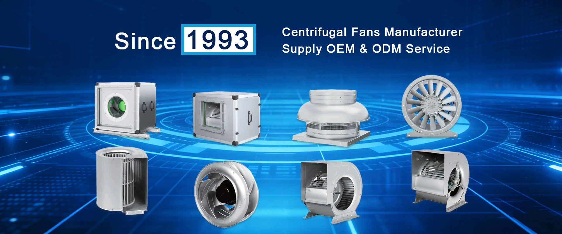
Most of our data center builds use a wall of YUWA units. An N+1 layout means one failed fan never causes a hotspot; the others compensate while it is replaced. There is no belt to service, and the modular units are light enough to move through standard doors without a crane.
Air-cooled and evaporative cooling units
For air-cooled chillers and indirect evaporative cooling, the AXF axial fan handles outdoor air from -40C to 65C. It runs on the same EC control platform, so the BMS sees indoor and outdoor fans the same way.
Why buying from the factory matters
We build the motor, controller, and impeller as one product in our own plant. That means spare parts, control options, and custom airflow targets all come from one source. For large halls we can pre-configure Modbus addresses and control curves before the units leave the factory, which cuts commissioning time on site.
Control System and PLC Connection
In a data center, the PLC or BMS modulates every fan from the cooling controller. Because the driver is built into the motor, the PLC sees each fan as a standard addressable device.
|
Control Input |
Motor Terminals |
PLC Connection |
|
0-10V analog |
VSP, GND |
PLC analog output; 0V = minimum speed, 10V = full speed |
|
PWM |
PWM, GND |
PLC pulse output; 0-100% duty cycle sets speed |
|
Modbus RTU / RS485 |
RSA+, RSB- |
PLC or HMI as Modbus master; reads status and alarms, writes speed |
All three options can be wired from the same PLC cabinet. 0-10V is the simplest wiring for a single speed command; Modbus RTU is chosen when the PLC or BMS needs two-way data, run status and fault feedback.
Recommended Models and Specifications
|
Model |
Type |
Size |
Airflow m3/h |
Pressure Pa |
Power |
Temp C |
|
YUWA |
EC plug fan |
400-630 mm |
1,000-24,000 |
0-2,500 |
1.1-7.5 kW |
-25 to 40 |
|
AXF |
EC axial fan |
710-950 mm |
10,000-35,000 |
0-300 |
1.5-4.5 kW |
-40 to 65 |
|
YUWE |
EC plug fan |
133-630 mm |
300-22,000 |
0-1,200 |
0.5-4.5 kW |
-25 to 40 |


FAQ
Do the fans support 24/7 operation?
Yes. They are rated for continuous duty, and the direct-drive design has no wear parts that need regular replacement.
What happens if one fan stops?
In an N+1 fan wall the remaining units raise their speed to hold total airflow, so the aisle stays cool until the unit is swapped.
Can we monitor every fan from the BMS?
Modbus RTU over RS485 is standard, alongside 0-10V and PWM. Speed, alarms, and status are visible to the management system.
Call to Action