

Fan Wall (FanGrid): Technical Overview, R&D Architecture and Application Guide
By Midi Industrial
1. What Is a Fan Wall (FanGrid)
A Fan Wall-also known as a FanGrid-is a modular air-moving system developed by Midi Industrial that replaces a single large traditional fan with an array of multiple small EC direct-drive centrifugal or plenum fans operating in parallel inside a common plenum chamber.
Unlike the conventional "single large impeller" approach, Midi Industrial's FanGrid uses a matrix of intelligent fan modules to share the air-delivery duty, featuring built-in redundancy, variable-speed control, and uniform airflow distribution that fully covers the entire face of coils, filters, and heat exchangers.
Midi Industrial positions the FanGrid not as a simple fan assembly, but as an integrated "smart air" platform-deeply fusing the fan itself, EC motor, drive electronics, and control logic within a modular architecture.
2. Midi Industrial R&D and Design Architecture
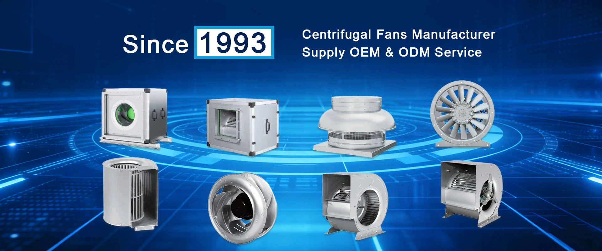
Founded in 1993, Midi Industrial has evolved from a conventional fan manufacturer into a fan-and-intelligent-motor system integrator. Its FanGrid development is built on three layers:
2.1 Core Fan Modules
Midi Industrial's FanGrid building blocks are derived from its proprietary EC plenum fan families:
YUWA Series – EC external-rotor brushless DC motor + aluminum airfoil impeller; up to ~25,000 m³/h per module, static pressure up to 1,600 Pa; designed for modular fan-wall configurations in AHUs and VAV systems.
YUWB / YUWE Series – Compact EC plenum fans (impeller 250–630 mm); airflow 600–22,000 m³/h; suitable for smaller AHUs, fresh-air units, and high-density arrays.
SYWA / SYWB Series – Airfoil backward-curved plenum fans (impeller 280–1,400 mm); AMCA-licensed for air performance, sound, and FEG; dynamically balanced to ANSI/AMCA 204 G2.5 or better.
Key aerodynamic and mechanical R&D points:
|
Design Element |
Technical Effect |
|---|---|
|
Backward-curved / airfoil blades |
Non-overloading power curve, high static efficiency |
|
Direct drive, no belt |
Low vibration, no periodic belt maintenance |
|
External-rotor PM brushless motor |
High efficiency, wide speed range, low inertia |
|
Precision balancing + FEA + destructive impeller testing |
Structural reliability, long service life |
2.2 Modular Mechanical Frame
Midi Industrial's fan wall frame design incorporates:
Standardized module pitch: Prevents aerodynamic interference between adjacent fans
Plenum depth optimization: CFD-validated to develop uniform inlet velocity distribution
Sealing plates, inlet cones, and baffles: Suppress edge recirculation and airflow short-circuiting
Hot-swappable mounting: Under N+1 standby, a single module can be withdrawn while remaining fans continue operating
Midi Industrial treats fan spacing, plenum geometry, and coil face velocity as integral product parameters-not secondary considerations.
2.3 Intelligent Control Layer
Each EC module in Midi Industrial's FanGrid carries integrated electronic control:
Speed control interfaces: 0–10 V / PWM / RS485 Modbus RTU
BMS / PLC integration: Reads RPM, power, temperature, fault codes
Closed-loop control strategies:
Constant static pressure (adapts to duct load variation)
Constant airflow (automatic filter clogging compensation)
Return-air temperature tracking (precision cooling in data centers, etc.)
Fault response mechanism: Detect failed module → isolate → automatically ramp up remaining modules to compensate airflow
This elevates the fan wall from passive hardware to an actively regulated air-delivery platform.
3. Working Principle
Multiple EC modules operate in parallel against the same system resistance curve:
Total airflow is the sum of operating-point airflow from all active modules, validated against the actual system curve-not a simple multiplication of free-air values.
Part-load operation: Shut down selected modules or reduce speed; remaining fans stay in their high-efficiency zone.
Fault condition: On single-module trip, the controller raises speed of surviving modules within allowable current/temperature limits to maintain design airflow.
Airflow uniformity: Full-face matrix delivery improves coil and filter utilization while reducing local hot spots.
Design note: Redundancy is not "add one extra fan." Midi Industrial's N+1 scheme is validated through fault simulation-with one module offline, the remaining units must still meet specified airflow, static pressure, distribution uniformity, and noise targets.
 4. Engineering Advantages
|
Advantage |
Technical Description |
|---|---|
|
Redundancy & uptime |
N+1 / N+2 hot standby; module maintenance without full-system shutdown |
|
Part-load energy savings |
EC motors maintain high efficiency at reduced speed, no damper throttling loss; retrofit projects often achieve 28%–50% fan-energy reduction |
|
Uniform airflow distribution |
Matrix layout flattens velocity profile across coil/filter face, improving heat exchange efficiency |
|
Modular scalability |
Modules can be added as load grows; blank-off plates allow future capacity expansion |
|
Low maintenance |
No belts or couplings; single-module field replacement; AMCA-certified performance |
|
Acoustic control |
Lower blade-passing frequency at part load; whole-array noise evaluated at system level |
5. Limitations and Design Discipline
High-static / long-duct systems: A single large fan is more economical; fan walls are not optimal here.
Module count requires planning: More fans is not always better-spacing, resonance risk, control complexity, and part-load profile must be balanced.
System curve validation required: Selection must be based on CFD analysis and measured system resistance; catalogue multiplication is insufficient.
Electronics environmental limits: EC drive electronics have maximum operating temperature; high-temperature environments require remote drives or enhanced cooling.
Electrical compatibility: Harmonic distortion (THDi) from large arrays must be managed in power distribution design.
6. Application Scenarios
6.1 Data Centers (CRAH / CRAC / Room Side Wall)
Midi Industrial EC FanGrid inside CRAH units or as side-wall air walls in server rooms
Demand-based cooling with precise supply-air temperature control, contributing to lower PUE
Single-fan failure does not compromise cabinet cooling; meets 24/7 operation requirements
6.2 Commercial AHU Retrofits
Replaces belt-driven centrifugal fans in legacy AHUs
Suitable for office buildings, airports, shopping malls in the 30,000–120,000 m³/h range
Significant part-load energy savings during night and transition seasons; quieter operation
6.3 Cleanrooms and Healthcare
Uniform laminar supply with redundant operation for continuity
Pharmaceutical facilities, hospital operating rooms, electronics fabrication plants
6.4 Industrial Plants
Transformer cooling, electrical room ventilation, metallurgical exhaust, chemical exhaust (corrosion-resistant options available)
Suitable for continuous production lines where downtime cost is extremely high
6.5 Special Environments
Wind tunnel testing, environmental simulation chambers, drone aerodynamic testing, and other scenarios requiring controllable wind fields
7. Midi Industrial FanGrid Selection Workflow
|
Step |
Content |
|---|---|
|
1 |
Define duty point: total airflow + system static pressure (include coil, filter, and duct losses) |
|
2 |
Map part-load profile-focus on actual operating distribution, not just peak demand |
|
3 |
Select module size from Midi Industrial's YUWA / YUWB / SYWA families (match impeller diameter, motor power, and efficiency curve) |
|
4 |
Lay out grid: rows × columns, module spacing, plenum depth; CFD check for flow uniformity |
|
5 |
Define redundancy level: validate N+1 through fault simulation (confirm remaining modules can hold design airflow, static pressure, and noise targets with one module offline) |
|
6 |
Configure control: communication protocol (Modbus/BMS), sensor feedback loops, alarm and interlock logic |
|
7 |
On-site verification: grid-point velocity measurement, power draw, noise level, and vibration testing |
Key sizing principle: Never size a fan wall by simply multiplying "number of fans × rated airflow per fan." Always cross-reference against the installed system resistance curve and validate part-load behavior.
8. Summary
Midi Industrial's Fan Wall (FanGrid) is not a row of fans. It is an engineered system combining:
High-efficiency EC airfoil plenum modules
Cube-frame modular mechanics
Smart distributed control
Validated redundancy and airflow uniformity
The value equation is:
Energy savings come from part-load operation · Reliability comes from redundancy · Flexibility comes from modularity · Success depends on control strategy
Midi Industrial's R&D focus-self-developed EC motors, AMCA-certified aerodynamics, and plug-and-play array architecture-makes the FanGrid suitable for data centers, AHU retrofits, cleanrooms, and industrial cooling where uptime and efficiency are both non-negotiable.